- 您现在的位置:买卖IC网 > Sheet目录342 > MC34844EP (Freescale Semiconductor)IC LED DVR BACKLIGHT 10CH 32QFN
�� �
�
�MC34844A�
�FUNCTIONAL� DESCRIPTION�
�FUNCTIONAL� INTERNAL� BLOCK� DESCRIPTION�
�Table� 12.� Operation� Current� Consumption� Modes�
�MODE�
�Manual�
�SM� Bus�
�EN� Pin�
�Low�
�High�
�Low�
�Low�
�Low�
�Low�
�SCK/SDA� Pins�
�Low�
�Low�
�Low� (>� 27� ms)�
�Active�
�Active�
�X�
�I� 2� C� Bit� Command�
�N/A�
�N/A�
�EN� bit� =� 0�
�EN� bit� =� 0�
�EN� bit� =� 1�
�SETI2C� bit� =� 1�
�CLRI2C� bit� =� 0�
�Current� Consumption�
�Mode�
�Shutdown�
�Operational�
�Shutdown�
�Sleep�
�Operational�
�I� 2� C� Low� Power�
�(Shutdown)�
�Comments�
�PWM� pin� =� Low�
�Part� Doesn’t�
�Wake-up�
�EN� bit� =� 0�
�SETI2C� bit� =� 1�
�I� 2� C�
�High�
�X�
�CLRI2C� bit� =� 0�
�Sleep�
�EN� bit� =� 0�
�SETI2C� bit� =� 1�
�High�
�X�
�CLRI2C� bit� =� 0�
�Operational�
�EN� bit� =� 1�
�BOOST�
�The� integrated� boost� converter� operates� in� non-�
�synchronous� mode� and� integrates� a� 2.5� A� FET.� An� integrated�
�sense� circuit� is� used� to� sense� the� voltage� at� the� LED� current�
�mirror� inputs� and� automatically� sets� the� boost� output� voltage�
�(DHC)� to� the� minimum� voltage� needed� to� keep� all� LEDs�
�biased� with� the� required� current.� The� DHC� is� designed� to�
�operate� for� pulse� widths� >� 400� ns� in� the� LED� drivers.�
�If� the� pulse� widths� are� shorter� than� specified,� the� DHC�
�circuit� will� not� operate� and� the� voltage� across� the� LED� drivers�
�will� increase� to� a� value� given� by� the� OVP� minus� the� total� LED�
�voltage� in� the� LED� string.� Therefore� it� is� imperative� to� select�
�the� proper� OVP� level� to� minimize� power� dissipation.�
�The� user� can� program� the� boost� frequency� by� I� 2� C�
�(BST[1:0])� only� after� the� IC� is� powered� up� and� before� the�
�boost� circuit� is� turned� ON� for� the� first� time� (PWM� pin� low� to�
�high).� This� sequence� avoids� boost� frequency� to� be� changed�
�inadvertently� during� operation.� The� first� I� 2� C� command� has� to�
�wait� for� 5.0� ms� after� the� part� is� turned� ON,� in� order� to� allow�
�sufficient� time� for� the� device� power� up� sequence� to� be�
�completed.�
�Please� follow� this� sequence� in� order� to� change� the� Boost�
�frequency� thru� I2C:�
�1.� Take� PWM� pin� low�
�normal� quiescent� operating� temperature� and� thereby�
�experience� a� forward� voltage� change,� typically� an� increase� in�
�the� forward� voltage.� This� change� can� be� significant� for�
�applications� with� a� large� number� of� series� LEDs� in� a� string�
�operating� at� high� current.� If� the� boost� controller� did� not� track�
�this� increased� change,� the� potential� on� the� LED� drivers� would�
�saturate� for� a� few� cycles� once� the� LED� channels� are� re-�
�enabled.�
�HARDWARE� AND� SOFTWARE� OVP� :�
�The� OVP� value� should� be� set� to� a� higher� value� than� the�
�maximum� LED� voltage� over� the� whole� temperature� range.� A�
�good� practice� is� to� set� it� 5.0� V� or� so� above� the� max� LED�
�voltage.�
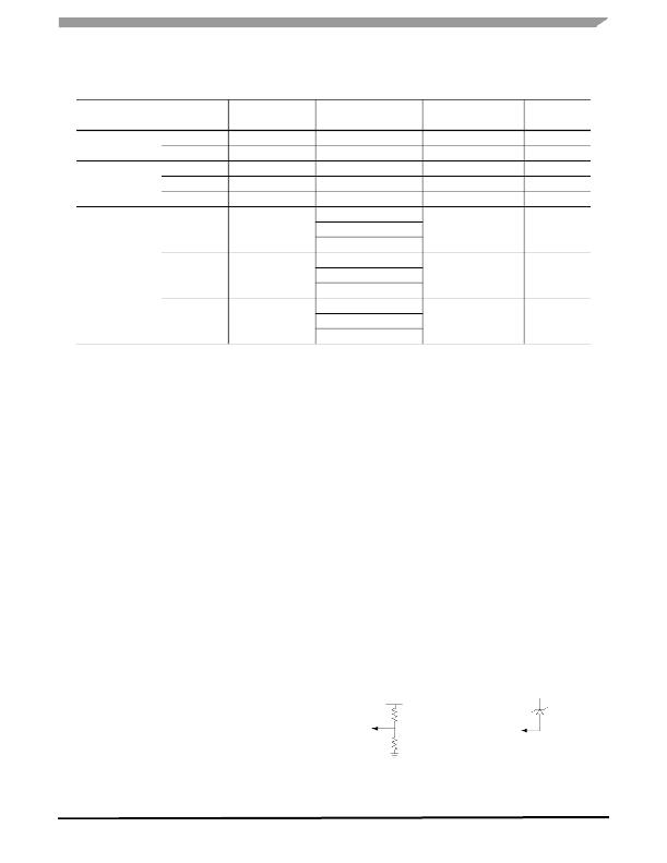
�The� OVP� can� be� set� from� 11� to� 62� V,� ~4.0� V� spaced,� using�
�the� I� 2� C� interface� (OVP� Register).� If� the� I� 2� C� capability� is� not�
�present,� the� OVP� can� be� controlled� either� by� a� resistor� divider�
�connected� from� VOUT� to� GND,� with� its� mid� point� tied� to� the�
�A0/SEN� pin,� or� by� a� zener� diode� from� VOUT� to� the� A0/SEN�
�pin� (threshold� =� 6.5� V).� During� an� OVP� condition,� the� output�
�voltage� will� go� to� the� OVP� level,� which� is� programmed� via� the�
�I� 2� C� interface� or� settled� by� a� resistor� divider� on� A0/SEN� pin,� or�
�by� a� zener� diode.� The� formulas� to� calculate� the� hardware�
�OVP� using� any� of� the� two� methods� are� as� follows:�
�2.� Disable� the� part� by� software� (EN� bit� =� low)�
�3.� Write� the� new� Boost� frequency� data� (BST[1:0])�
�4.� Enable� the� part� by� software� (EN� bit� =� high)�
�Method� 1�
�V� OUT�
�Method� 2�
�V� OUT�
�5.� Reconfigure� all� registers�
�6.� Take� PWM� pin� High�
�The� boost� controller� has� an� integral� track� and� hold�
�A0/SEN�
�RUPPER�
�RLOWER�
�A0/SEN�
�VZENER2�
�OVP� =� V� ZENER2� +� 6.5� V�
�amplifier� with� indefinite� hold� time� capability,� to� enable�
�immediate� LED� on� cycles� after� extended� off� times.� During�
�OVP� =� 6.5� V� [(R� UPPER� /� R� LOWER� )� +� 1]� +� (100E-6� x� R� UPPER� )�
�extended� off� times,� the� external� LEDs� cool� down� from� their�
�34844A�
�Analog� Integrated� Circuit� Device� Data�
�Freescale� Semiconductor�
�45�
�发布紧急采购,3分钟左右您将得到回复。
相关PDF资料
MC34845AEPR2
IC LED DVR BACKLIGHT 6CH 24QFN
MC34845BEPR2
IC LED DVR BACKLIGHT 6CH 24QFN
MC34848EPR2
IC LED DVR BACKLIGHT 8CH 48QFN
MC56F8006DEMO-T
BOARD DEMO FOR MC56F8006 DSP
MCB1114
BOARD EVALUATION FOR NXP LPC1114
MCB11C14
BOARD EVAL FOR NXP LPC11C14
MCB2470
BOARD EVAL NXP LPC247X SERIES
MCBSTM32EXL
BOARD EVALUATION FOR STM32F103ZE
相关代理商/技术参数
MC34844EPR2
功能描述:LED照明驱动器 BACKLIGHT LED DRIVER W/10 CHANNELS RoHS:否 制造商:STMicroelectronics 输入电压:11.5 V to 23 V 工作频率: 最大电源电流:1.7 mA 输出电流: 最大工作温度: 安装风格:SMD/SMT 封装 / 箱体:SO-16N
MC34845
制造商:SPC Multicomp 功能描述:RECEPTACLE FREE 16WAY 制造商:SPC Multicomp 功能描述:RECEPTACLE, FREE, 16WAY
MC34845AEP
功能描述:LED照明驱动器 6-Ch LED Backlt Driver RoHS:否 制造商:STMicroelectronics 输入电压:11.5 V to 23 V 工作频率: 最大电源电流:1.7 mA 输出电流: 最大工作温度: 安装风格:SMD/SMT 封装 / 箱体:SO-16N
MC34845AEPR2
功能描述:LED照明驱动器 6-Ch LED Backlt Driver RoHS:否 制造商:STMicroelectronics 输入电压:11.5 V to 23 V 工作频率: 最大电源电流:1.7 mA 输出电流: 最大工作温度: 安装风格:SMD/SMT 封装 / 箱体:SO-16N
MC34845BEP
功能描述:USB 接口集成电路 6-Ch LED Backlt Driver RoHS:否 制造商:Cypress Semiconductor 产品:USB 2.0 数据速率: 接口类型:SPI 工作电源电压:3.15 V to 3.45 V 工作电源电流: 最大工作温度:+ 85 C 安装风格:SMD/SMT 封装 / 箱体:WLCSP-20
MC34845BEPR2
功能描述:USB 接口集成电路 6-Ch LED Backlt Driver RoHS:否 制造商:Cypress Semiconductor 产品:USB 2.0 数据速率: 接口类型:SPI 工作电源电压:3.15 V to 3.45 V 工作电源电流: 最大工作温度:+ 85 C 安装风格:SMD/SMT 封装 / 箱体:WLCSP-20
MC34845CEP
功能描述:LED照明驱动器 6-Ch LED Backlt Driver RoHS:否 制造商:STMicroelectronics 输入电压:11.5 V to 23 V 工作频率: 最大电源电流:1.7 mA 输出电流: 最大工作温度: 安装风格:SMD/SMT 封装 / 箱体:SO-16N
MC34845CEPR2
功能描述:LED照明驱动器 6-Ch LED Backlt Driver RoHS:否 制造商:STMicroelectronics 输入电压:11.5 V to 23 V 工作频率: 最大电源电流:1.7 mA 输出电流: 最大工作温度: 安装风格:SMD/SMT 封装 / 箱体:SO-16N